The content below is taken from the original ( Exploring The Raspberry Pi 4 USB-C Issue In-Depth), to continue reading please visit the site. Remember to respect the Author & Copyright.
It would be fair to say that the Raspberry Pi team hasn’t been without its share of hardware issues, with the Raspberry Pi 2 being camera shy, the Raspberry Pi PoE HAT suffering from a rather embarrassing USB power issue, and now the all-new Raspberry Pi 4 is the first to have USB-C power delivery, but it doesn’t do USB-C very well unless you go for a ‘dumb’ cable.
Join me below for a brief recap of those previous issues, and an in-depth summary of USB-C, the differences between regular and electronically marked (e-marked) cables, and why detection logic might be making your brand-new Raspberry Pi 4 look like an analogue set of headphones to the power delivery hardware.
A Trip Down Memory Lane
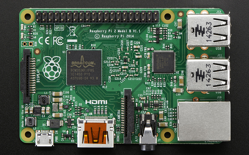
Back in February of 2015, a blog post on the official Raspberry Pi blog covered what they figured might be ‘the most adorable bug ever‘. In brief, the Raspberry Pi 2 single-board computer (SBC) employs a wafer-level package (WL-CSP) that performs switching mode supply functionality. Unfortunately, as is the risk with any wafer-level packaging like this, it exposes the bare die to the outside world. In this case some electromagnetic radiation — like the light from a xenon camera flash — enter the die, causing a photoelectric effect.
The resulting disruption led to the chip’s regulation safeties kicking in and shut the entire system down, fortunately without any permanent damage. The fix for this is to cover the chip in question with an opaque material before doing something like taking any photos of it with a xenon flash, or pointing a laser pointer at it.
While the Raspberry Pi 2’s issue was indeed hard to predict and objectively more adorable than dangerous, the issue with the Power over Ethernet (PoE) HAT was decidedly less cute. It essentially rendered the USB ports unusable due to over-current protection kicking in. The main culprit here is the MPS MP8007 PoE power IC (PDF link), with its relatively sluggish flyback DC-DC converter implementation being run at 100 kHz (recommended <200 kHz in datasheet). Combined with a lack of output capacity (41% of recommended), this meant that surges of current were being passed to the USB buffer capacitors during each (slow) power input cycle, which triggered the USB chipset’s over-current protection.
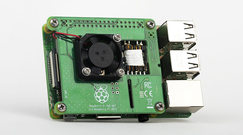
The solution here was a redesign of the PoE HAT, which increased the supply output capacitance and smoothed the output as much as possible to prevent surges. This fixed the problem, allowing even higher-powered USB devices to be connected. The elephant-sized question in the room was of course why the Raspberry Pi team hadn’t caught this issue during pre-launch testing.
USB Type-C is Far More Than Just a Connector
The new Raspberry Pi 4 was just released a few weeks ago, and is the biggest overhaul of the platform since the original Model B+ that defined the ‘Raspberry Pi form factor‘. But in less than a week we started hearing about a flaw in how the USB-C power input was behaving. It turns out the key problem is when using electronically marked cables which include circuitry used by the USB-C specification to unlock advanced features (like supplying more power or reconfiguring what signals are used for between devices). These e-marked cables simply won’t work with the Pi 4 while their “dumb” cousins do just fine. Let’s find out why.
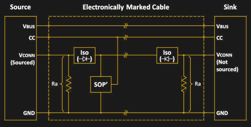
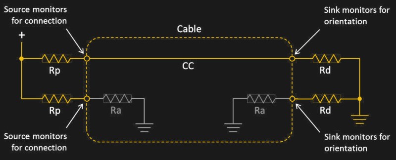
The USB-C specification is quite complex. Although mechanically the USB-C connector is reversible, electrically a lot of work is being performed behind the scenes to make things work as expected. Key to this are the two Configuration Channel (CC) pins on each USB-C receptacle. These will each be paired to either the CC wire in the cable or (in an e-marked cable) to the VCONN conductor. A regular USB-C cable will leave the VCONN pin floating (unconnected), whereas the e-marked cable will connect VCONN to ground via the in-cable Ra resistor as we can see in this diagram from the USB-C specification.
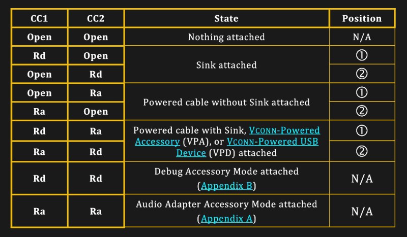
It’s also possible to have an e-marked USB-C cable without the VCONN conductor, by having SOP ID chips on both ends of the cable and having both the host and the device supply the cable with VCONN. Either way, both the host and device monitor the CC pins on their end measure the resistance present through the monitored voltage. In this case, the behavior of the host is dictated by the following table:
The Analog Raspberry Pi 4
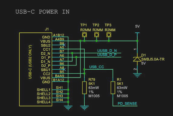
Now that we have looked at what a basic USB-C setup looks like, it’s time to look at the subject of this article. As the Raspberry Pi team has so gracefully publicized the Raspberry Pi 4 schematics (minus the SoC side for some reason), we can take a look at what kind of circuit they have implemented for the USB-C sink (device) side:
As we can see here, contrary to the USB-C specification, the Raspberry Pi design team has elected to not only connect CC1 and CC2 to the same Rd resistor, but also shorted CC1 and CC2 in the process.
Remember, the spec is looking for one resistor (Rd) on each of the two CC pins. That way, an electronically marked cable connecting the Pi 4 board and a USB-C charger capable of using this standard would have registered as having the appropriate Rd resistance, hence 3A at 5V would have been available for this sink device.
 Since this was however not done, instead we get an interesting setup, where the CC connection is still established, but on the Raspberry Pi side, the resistance doesn’t read the 5.1 kOhm of the Rd resistor, as there’s still the Ra resistor in the cable on the other CC pin of the receptacle. The resulting resistor network thus has the values 5.1k and 1k for the Rd and Ra resistors respectively. This circuit has an equivalent circuit resistance of 836 Ohm.
This value falls within the range permitted for Ra, and thus the Raspberry Pi 4 is detected by the source as Ra + Ra, meaning that it is an audio adapter accessory, essentially a USB-C-to-analog audio dongle. This means that the source does not provide any power on VBUS and the Raspberry Pi 4 will not work as it does not get any power.
In the case of a non-electronically marked cable, this would not be an issue as mentioned earlier, as it doesn’t do this form of detection, with no Ra resistor to get in the way of making the Raspberry Pi 4 do its thing.
Testing is More Important than Developing
Much like with the PoE HAT issue, the question was quickly raised: why wasn’t this issue with the Raspberry Pi 4’s USB-C port found much sooner during testing. Back with the Pi 2 PoE HAT, the official explanation from the Raspberry Pi team was that they had not tested with the appropriate devices, had cut back on testing because they were late with shipping and did not ask the field testers the right questions, leading to many scenarios simply not being tested.
In a response to Tech Republic, the CEO of Raspberry Pi Ltd, Eben Upton has admitted to the Pi 4 USB-C error. And a spokesperson for Raspberry Pi Ltd said in a response to Ars Technica that an upcoming revision of the Raspberry Pi 4 is likely to appear within the “next few months”.
It seems obvious how The obvious cause for why this error managed to sneak its way into production. production seems obvious. Much like with the PoE HAT, a design flaw snuck in, no one caught it during schematic validation, the prototype boards didn’t see the required amount of testing (leaving some obvious use cases untested), and thus we’re now seeing another issue that leaves brand new Raspberry Pi hardware essentially defective.
Sure, it’s possible to hack these boards as a workaround. With the PoE HAT one could have soldered on a big electrolytic capacitor to the output stage of the transformer’s secondary side and likely ‘fixed’ things that way. Similarly one could hack in a resistor on the Raspberry Pi 4 after cutting a trace between both CC pins… or even simpler: never use an e-marked USB-C cable with the Raspberry Pi 4.
Yet the sad point in all of this is undoubtedly that these are supposed to be ready-to-use, fully tested devices that any school teacher can just purchase for their classroom. Not a device that first needs a trip down to the electronics lab to have various issues analyzed and bodge wires and components soldered onto various points before being stuffed into an enclosure and handed over to a student or one’s own child.
The irony in all of this is that because of these errors, the Raspberry Pi team has unwittingly made it clear to many that testing hardware isn’t hard, it just has to be done.
Compliant USB-C is Not Easy
In the course of writing this article, yours truly had to dive deep into the USB-C specification, and as a point of fairness to the Raspberry Pi design team, the first time implementing USB-C is not a walk in the park. Of all specifications out there, USB-C does not rank very high in user-friendliness or even conciseness. It’s a big, meandering, 329 page document, which does not even cover the monstrosity that’s known as USB-C Power Delivery.
Making a mistake while implementing a USB-C interface during one’s first time using it in a design is not a big shame. The USB-C specification adds countless details and complexities that simply do not exist in previous versions of the USB standard. Having this mess of different types of cables with many more conductors does not make life easier either.
The failure here is that the USB-C design errors weren’t discovered during the testing phase, before the product was manufactured and shipped to customers. This is something where any team that has been involved in such a project needs to step back and re-evaluate their testing practices.


