The content below is taken from the original ( Raspberry Pi’s Power Over Ethernet Hardware Sparks False Spying Hubbub), to continue reading please visit the site. Remember to respect the Author & Copyright.
Have you ever torn open an Ethernet jack? We’d bet the vast majority of readers — even the ones elbow-deep into the hardware world — will answer no. So we applaud the effort in this one, but the conclusion landed way off the mark.
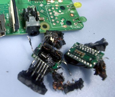
In the last few days, a Tweet showing a Raspberry Pi with its Ethernet socket broken open suggested the little PCB inside it is a hidden bug. With more going on inside than one might expect, the conclusion of the person doing the teardown was that the Raspberry Pi foundation are spying upon us through our Ethernet traffic. That’s just not the case. But we’re still excited about what was found.
 The truth is rather more obvious to anyone who has spent a lot of time working with Ethernet interfaces. To confirm our suspicions we had a chat with Roger Thornton, the Principal Hardware Engineer at Raspberry Pi Trading, and the man with his finger on the pulse of what goes into a Pi. He was very happy to confirm in a fascinating conversation about sourcing Ethernet jacks with integrated magnetics, that of course the Pi contains no surveillance hardware. Instead what our Tweeter had found are the magnetics, the isolation transformer, and some filter components included because the latest Raspberry Pi version (Raspberry Pi 3 Model B+) has support for a future Power Over Ethernet (PoE) add-on.
It is these filter parts on their little PCB that seem to have captured attention as possible nefarious parts, but in debunking the whole idea it’s worth taking a look at the magnetics themselves because they are an interesting and above all inexpensive part that has some uses outside the world of Ethernet.
What Goes Into an Ethernet Jack Anyway?

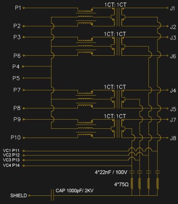
[Roger] was kind enough to give us the schematic of the jack used in the Pi, though it is typical of such jacks and bears very little difference from that you’d find in any number of other nearly identical components. At its centre are a row of four transformers, which serve to isolate the Pi from whatever stray voltages may be present upon the Ethernet cabling. To the left of each transformer is a trifilar choke to cancel out any common-mode noise that may have arrived via the cable. At the bottom is a set of RC filters on the PoE power lines which were probably the components that ignited the controversy.
The transformers have a bandwidth from about 250 kHz to 100 MHz which allows them to ignore the low frequency 48 VAC of the PoE, and pass through the Ethernet signals. In the case of the Pi 3 B+, the PoE lines are taken to a header on the board, which will mate with an upcoming PoE HAT that will contain a switching PSU with its own 1.5 kV isolation transformer to preserve the barrier between the Pi and the line.
An interesting aside to the conversation came in that some companies wind their own transformers while others buy ready-made ones. An easy way to spot the in-house ones it seems is that they will usually be concealed under some black sealant as is the case with the one in the Tweet, while the bought-in ones will be standalone potted components.
Hacking Ethernet Components

So with [Roger]’s help we’ve established that the Pi contains no nefarious components (which of course we knew anyway). But there remains the discovery that every Ethernet card ever made has at least one transformer with a very usable RF bandwidth, so these are components very much worth a second look if you have an interest in radio. If you have ever needed a small RF transformer for inter-stage coupling you will be aware that these are not cheap components, so the thought that there is a ready supply that you can either lift from an old Ethernet-connected device (or buy for only a bit more than pennies) is of great interest.
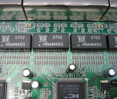
Ethernet transformers are available in a range of packages, from those built-in to sockets like the one on the Pi through various surface-mount packages and even through-hole versions on older devices. They come in three main categories which as you might expect correspond to the different Ethernet standards. 10 Mbit components usually have two transformers in one package and a bandwidth from about 100 kHz to 10 MHz, 100 Mbit ones have two with a 300 kHz to 100 MHz bandwidth, and 1000 Mbit ones like the Pi component described above have four 300 kHz to 100 MHz transformers. The transformers themselves are wound onto tiny ferrite rings, and are almost always 1:1 centre-tapped with a 600 Ω impedance and a common-mode choke on one side as described above.

Within those limitations they can be used for a variety of small-signal RF tasks that can work within those impedance ranges. By using only one half of the winding that doesn’t have the common-mode choke they can be configured as a 1:2 transformer with a 300 Ω input and a 600 Ω output, for example. In bandwidth terms they also have useful performance some way beyond their advertised specification, for example here in Europe they will pass through long wave broadcast stations at around 150 kHz to 200 kHz, and at the other end of their range they will pass through FM broadcast stations at 108 MHz. Within that range you have the entirety of HF and the lower end of VHF, allowing for example the use within every amateur band from the MF bands to 6 m and 4 m if your country has an allocation. Where this is being written they are the go-to transformer in homebrew receivers and small-signal stages for example, where they are infinitely preferable to winding a toroid.
Sometimes it is easy to believe that an application-specific component such as an Ethernet transformer could have no other uses, but it’s worth reading data sheets and asking the question as to whether any useful components lurk unnoticed in your junk bin. Take a second look, you’d be surprised what you might find!


